


A clutch player in the knifemaker’s shop, the tire hammer gives more control than other D.I.Y. power hammers.
Like a variable-speed hand drill, your backyard power hammer should be able to run slowly, at full speed or in between, depending on the task. The simplest way to guarantee it does this is to use a slipping clutch.
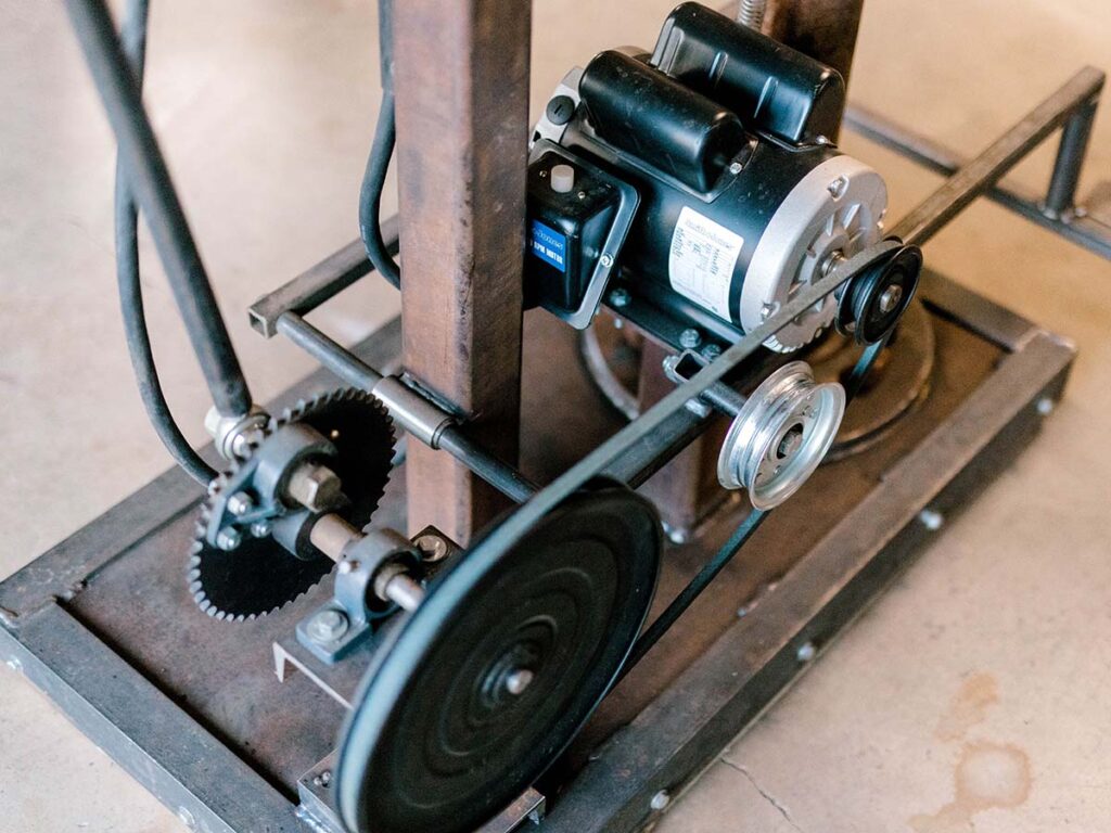
There are two main designs of slipping clutch. One uses a slack belt, a flywheel and pulleys. The drive pulley rotates within a slack belt. The foot pedal linkage pushes an idler wheel into the slack belt, increasing the belt tension to the point that the belt begins to turn the pulley on the flywheel.
Another design uses a tire clutch, where the foot pedal linkage pushes a drive wheel into an automobile tire, with the hub of the tire serving as the flywheel. The most common “tire hammer” design uses a similar clutch but turned the other way and connected to a linkage. Your available parts will dictate your design.
Why A Clutch
A function of the clutch is to reduce the RPM of the motor speed to get the hammer rate of beats per minute (BPM) into a safe and useful range. You want the hammer rate to generally end up between 150 and 250 BPM, though many variables change with each hammer. In general, a heavier tup (aka hammer head assembly) requires a slower BPM, whereas a lighter hammer can have a higher BPM. You do not want your hammer running faster than you can control it, nor so fast that the inherent forces tear it apart. My hammer uses a 24-inch tire and a 3-inch drive wheel for an 8:1 reduction of a 1750 RPM motor, yielding a calculated 218 BPM at full speed. Your hammer will run differently depending on your motor RPM, your drive and driven wheel diameters, and the hammer’s overall design. I rarely run my hammer full speed during general forging work, and the tire clutch gives good speed control. Full speed works acceptably well for drawing out damascus billets or breaking down large stock.
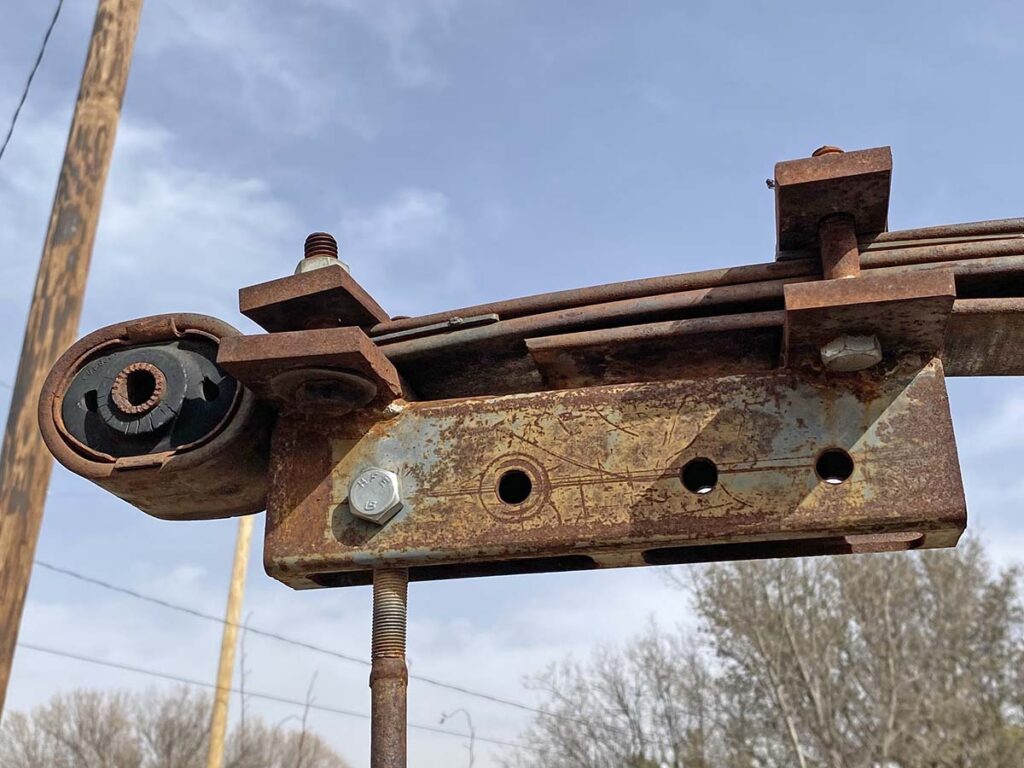
My tire clutch has an integral flywheel bolted to the hub. On the flywheel I welded several different nuts for attaching the pitman arm (for more on the pitman arm, see part three last issue). Each nut is a different distance from the center of the hub. This allows me to vary the length of the stroke, in my case between 6.5, 7 and 7.5 inches, based on where I connect the arm to the flywheel. Coupled with an adjustable-length pitman arm, this setup allows a degree of tuning to get the hammer hitting in a way that transfers the power directly to the workpiece with efficiency, yet in a way that doesn’t place undue stress on the hammer itself.
Choosing A Motor For Your Tire Hammer
As for motors, the size may vary a bit depending on the overall tup weight of your hammer. For most homebuilt hammer sizes, a 1 or 1.5 HP motor is plenty. My 40-pound hammer uses a 1.5 HP motor running on 110v and does not trip a standard 15-amp breaker, suggesting that 1.5 HP is more than plenty for a 40-pound head. Whether the motor runs on 110v or 220v will depend on your shop setup and what you have available, but you’d be best served either way with a motor that runs in the 1700 RPM range, not one that runs in the 3400 RPM range. There’s no need to go three phase or variable speed unless you’re already set up for either.
You will need an on/off switch for your motor. To run the hammer, turn the motor on, then use the foot pedal linkage to engage the clutch.
Sourcing Dies
Most power hammers have a set of dies in between the anvil and the hammer shaft. Dies may be built in a variety of shapes and sizes, depending on how you want your hammer to move the metal. Two basic die designs are flat and crowned. Flat dies move the metal somewhat equally in all four directions, while crowned dies will draw out the length of your workpiece perpendicular to the crown on the dies. Some smiths design their hammers to accommodate various top or bottom tools, or spring swages as well.
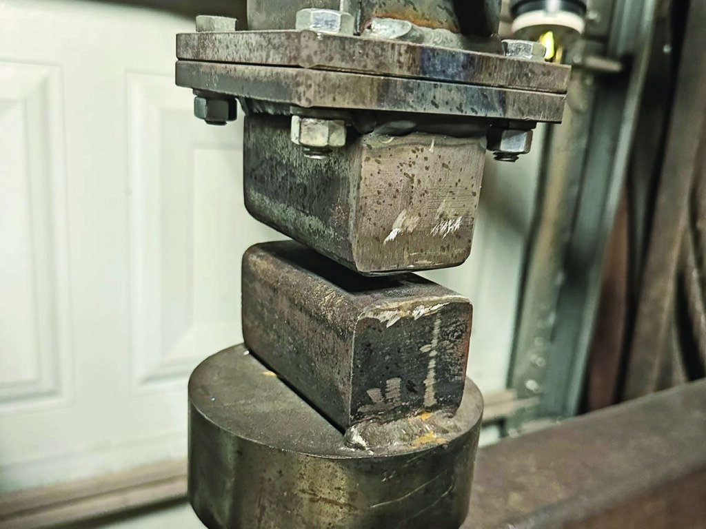
On my personal hammer, the dies are built out of 1.5-inch square 4140 steel bar stock, heat treated and ground essentially flat, with slightly radiused corners. Some hammers are set up with dies that are interchangeable but mine is not. Full disclosure: My die attachment is one point of weakness in my design. I ultimately welded my bottom die plate straight to the anvil, and I’ve had to reinforce the top die connection and re-weld it several times. Perhaps a more skilled welder could have done better!
Creative Necessity
I can’t emphasize enough the creativity necessary to build a functioning power hammer from scrap. It’s one thing to watch a YouTube video and think, “It must be nice to have a power hammer.” It’s another thing entirely to watch the same video and try to discern how the rocker arm connects to the center post, or how the tire clutch axle is set up.
At the time of my hammer build, there was an online gallery hosted in Czechoslovakia that had hundreds of pictures of various homebuilt and factory built hammers. I couldn’t have built mine without those examples. I don’t speak Czech but the pictures tell the story well.
Read More On Power Hammers:
- How To Build An Appalachian Spring Helve Hammer
- D.I.Y. Power Hammer Parts: Scrapping Together Your Project
- D.I.Y. Power Hammer: Do You Really Need One?
 NEXT STEP: Download Your Free KNIFE GUIDE Issue of BLADE Magazine
BLADE’s annual Knife Guide Issue features the newest knives and sharpeners, plus knife and axe reviews, knife sheaths, kit knives and a Knife Industry Directory.Get your FREE digital PDF instant download of the annual Knife Guide. No, really! We will email it to you right now when you subscribe to the BLADE email newsletter.


Is their a video to show how it works?